

Will AI Replace Linux Device Driver Engineers?
AI can generate code snippets, explain kernel errors and create basic driver templates. But making a driver work reliably on real hardware is still an engineering responsibility.
Kernel Masters practical estimate based on training and hardware-development experience.
Short Answer: No.
AI is a powerful assistant, but Linux device driver development is not only about producing C code. The difficult work is understanding the hardware, integrating it with the kernel, measuring what is happening on a board, finding timing and memory problems, and validating the final system.
Artificial Intelligence is transforming many areas of software development. Today, AI tools can generate code snippets, explain kernel errors, and even create basic Linux driver templates within seconds.
This has led many students and professionals to ask an important question: “Will AI replace Linux Device Driver Engineers?”
The short answer is: No.
AI can help with a small portion of the work, but the majority of real-world Linux Device Driver development still depends on human engineers with strong hardware and debugging skills.
At Kernel Masters, based on our practical training and hardware-development experience, we estimate that AI can assist with roughly 5% of the overall work, while experienced engineers remain responsible for the remaining 95%.
The Difference Between Writing C Code and Building a Working Driver
Many beginners think a Linux driver is just a C program.
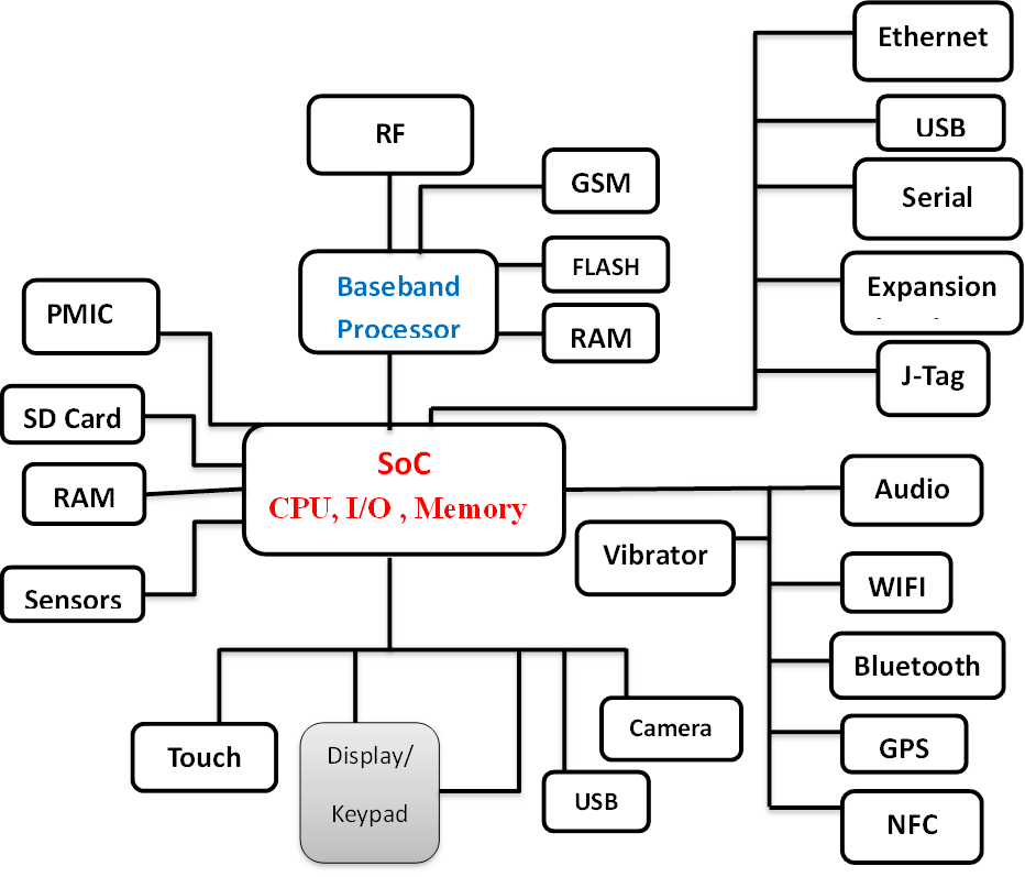
In reality, a driver sits at the boundary between software and hardware.
A successful driver requires knowledge of:
- Hardware architecture
- Datasheets and errata
- Interrupts and DMA
- Device Tree integration
- Power sequencing
- Memory coherency
- Kernel internals
- Performance optimization
- Real hardware debugging
- Validation and reliability
The 4 Main Reasons AI Cannot Write a 100% Working Linux Device Driver
1
Hardware Datasheets and Errata Contain Critical “Secret” Knowledge
Every embedded processor, camera sensor, NPU, SPI device, or I²C peripheral comes with large technical documentation.
Indicative documentation ranges: actual document volume varies by vendor, device family and product maturity.
| Hardware Type | Typical Documentation Size |
|---|---|
| Microcontrollers | 500–1500 pages |
| Application processors | 2000+ pages |
| Camera sensors | 800–2000 pages |
| NPUs / AI accelerators | 1000–3000 pages |
The most important information is often not obvious. A vendor may include a device-specific note such as:
0x43, bit 3, before enabling DMA; otherwise the system may hang.Such requirements may appear in hardware errata sheets, vendor application notes, internal engineering documents or NDA-protected updates.
Why AI Fails Here
AI can only reason from the technical information made available to it. It may not have access to confidential errata, vendor support history, internal workarounds or proprietary initialization sequences.
As a result, AI may generate code that looks correct but fails on real hardware.
What Human Engineers Do
- Read hundreds of pages of documentation
- Identify hidden initialization requirements
- Compare datasheet and errata revisions
- Test different register sequences
- Validate behaviour on actual boards
This is a hardware engineering task, not just a coding task.
2
Real Hardware Debugging Cannot Be Automated by AI
A driver does not operate in isolation. It interacts with interrupt controllers, DMA engines, caches, clocks, power domains and external peripherals.
Many failures are caused by timing, ordering or hardware-state problems.
/* Interrupt arrives */
irq_handler();

/* Device-specific interrupt acknowledge */
writel(IRQ_CLEAR, base + STATUS_REG);

/* On some non-coherent streaming DMA paths,
 * synchronize before CPU access when required. */
dma_sync_single_for_cpu(dev, dma_addr, size, direction);
If the sequence or timing is wrong, the interrupt may repeat forever, DMA data may be corrupted, the kernel may crash intermittently, or the board may freeze only once every few hours.
How Engineers Debug This
Physical instruments
- Oscilloscope
- Logic analyzer
- JTAG debugger
- UART console
- Power measurement tools
Kernel-level tools
- Dynamic debug and kernel logs
- Ftrace and tracepoints
- KGDB / GDB where appropriate
- KASAN, lockdep and fault reports
- Subsystem-specific debug facilities
An engineer may need to measure an SPI clock, verify reset pulse width, check whether an interrupt line toggles, confirm DMA completion timing or observe power sequencing.
This is why debugging skills remain one of the most valuable abilities in embedded Linux development.
3
Every Board Requires Custom Integration
A common misconception is: “If the driver works on one board, it will work on another.”
A reusable driver may work across several boards, but every board still requires correct hardware description, resource configuration and validation.
Device Tree Problems
A driver may fail simply because the Device Tree is wrong.
&spi1 {
    status = "okay";
    pinctrl-0 = <&spi1_pins>;
};
A single incorrect pinmux setting can prevent the device from being created or the driver from binding correctly.
Power Sequencing Problems
Many peripherals require a strict sequence:
If the order is wrong, the device may not respond, the sensor may remain in reset, or—in poorly protected hardware—components may be stressed or damaged.
Memory Architecture Problems
DMA behaviour depends on whether memory is coherent, non-coherent, IOMMU-mapped, cached or non-cached. The correct implementation depends on the SoC, device and board design.
What Human Engineers Must Understand
- Board schematics
- Power rails
- Clock trees
- Reset circuits
- GPIO routing
- Memory architecture
- Kernel configuration
- Firmware description
AI does not know the complete behaviour of a custom board unless the relevant design information, constraints and measurements are supplied—and even then, the result must be verified on hardware.
4
Safety and Liability Require Human Responsibility
Imagine drivers used in automotive ADAS systems, medical equipment, aerospace electronics or industrial robots. A single bug can have serious consequences.
Responsible engineering teams will not release production driver code without human review, hardware validation, testing and accountable sign-off.
The Required Engineering Process
- Code review
- Hardware validation
- Stress testing
- Performance testing
- Safety analysis
- Documentation
- Regression testing
- Engineering sign-off
A human engineer must take responsibility for the final result.
What AI Can Actually Help With (≈ 5%)
AI is still useful. It can accelerate repetitive work and help engineers navigate information faster.
- Generate boilerplate probe/remove structures
- Create Device Tree node templates
- Explain common kernel errors
- Suggest register read/write helpers
- Summarize supplied datasheet sections
- Convert vendor code into cleaner Linux-style code
- Draft test checklists and documentation
- Compare patterns in existing drivers
static int my_probe(struct platform_device *pdev)
{
    /* Acquire resources and initialize the device */
    return 0;
}

static void my_remove(struct platform_device *pdev)
{
    /* Release resources not managed automatically */
}
This saves time, but it is only a small part of the complete project. Kernel APIs also evolve, so generated examples must always be checked against the target kernel version and subsystem documentation.
What Human Engineers Still Do (≈ 95%)
AI Assistance
- Templates
- Boilerplate
- Explanations
- Documentation support
Engineer Responsibility
- Understand hardware architecture
- Read datasheets and schematics
- Debug real hardware
- Analyze interrupts and DMA
- Fix races and lifetime bugs
- Optimize and validate reliability
These are the skills companies pay for.
The Most Valuable Skill: Hardware Debugging
The future of embedded Linux belongs to engineers who can answer questions such as:
- Why is the interrupt not triggering?
- Why is DMA returning corrupted data?
- Why does the board hang during boot?
- Why does the camera work only after reset?
- Why is performance limited to 10 FPS instead of 30 FPS?
- Why does suspend/resume fail only after repeated cycles?
These problems cannot be solved by copying code from the internet. They require observation, measurement, experimentation, reasoning and experience.
AI can suggest possibilities. The engineer must collect evidence, isolate the failure and prove the fix.
Why We Teach Real Hardware at Kernel Masters
At Kernel Masters, we focus on industrial embedded Linux training.
Students work with real development boards, oscilloscopes, logic analyzers, Linux kernel source code, Device Tree, U-Boot, custom drivers and performance profiling tools.
Our goal is not to create “code generators.”
Our goal is to create engineers who can bring up hardware, debug systems, and build real embedded products.
Final Takeaway
AI Is a Powerful Assistant—Not a Replacement for Embedded Linux Engineers
Remember this simple rule:
Boilerplate code, templates and explanations.
Hardware understanding, debugging, integration, optimization and validation.
The companies that build automotive systems, AI cameras, robotics platforms, medical devices and industrial products are not looking for people who can merely generate code.
They are looking for engineers who can understand hardware, debug complex systems, solve problems under pressure and deliver reliable products.
The Future Belongs to Engineers Who Can Debug Hardware—Not Just Write Code.
Kernel Masters
Industrial Embedded Linux and Linux Device Driver Training.
We Build Engineers, Not Just Programmers.


 Admission for 6 months Embedded AI & IoT offline course at Hyderabad & Bangalore