


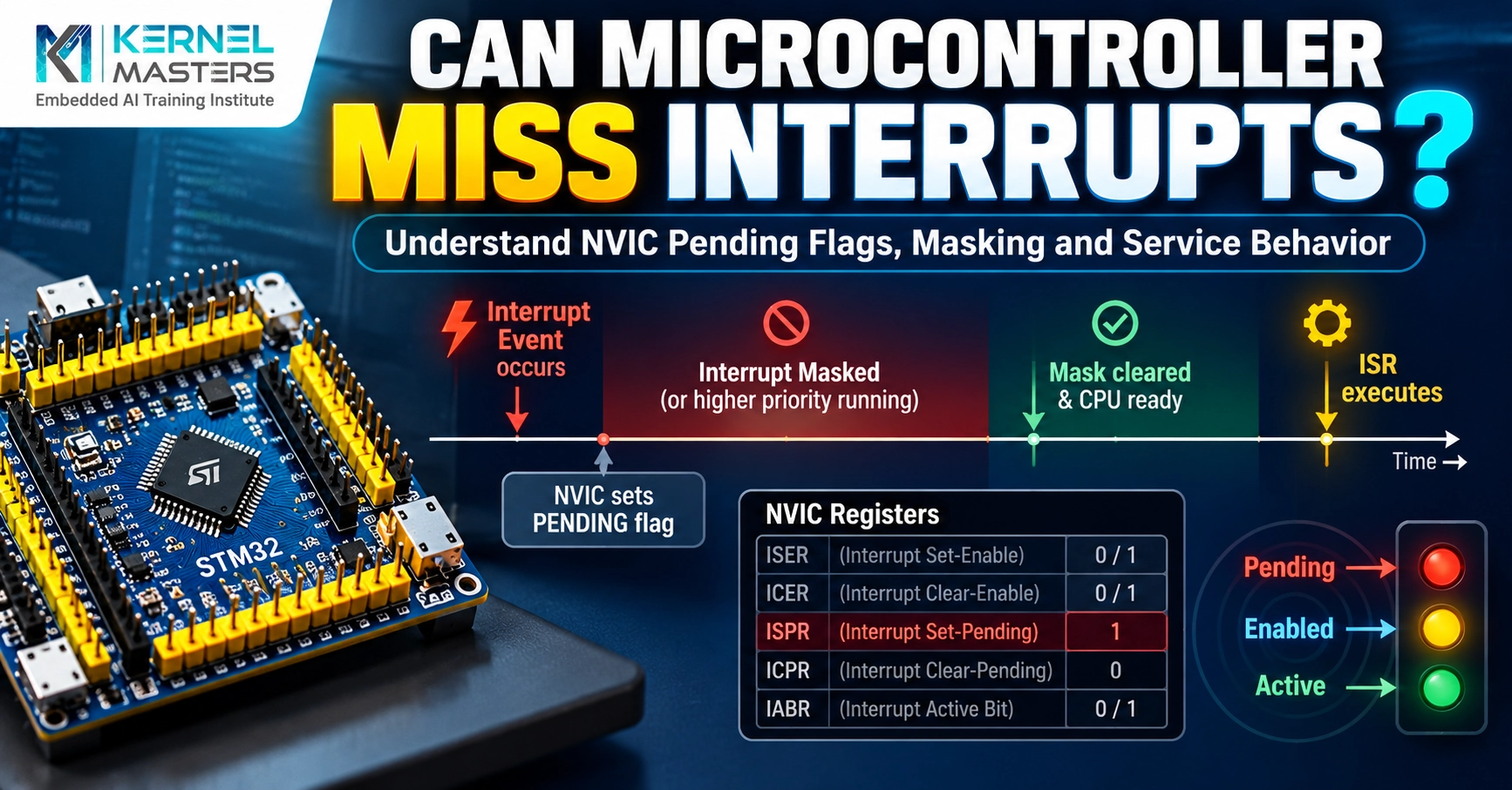
Imagine a sensor generates three short pulses while your microcontroller has interrupts temporarily masked.
When interrupts are unmasked, how many times will your Interrupt Service Routine (ISR) execute?
Pause and predict
Which claim is safe to make?
Yes. The request state, event storage and timing determine what can be serviced. The diagram below follows one specific case.
That outcome can occur, but “always” is too strong. Pending state does not count every event; peripheral storage and timing determine the result.
Reveal the explanation
Three times? Not necessarily. Several physical events can leave a single pending indication. The exact result depends on the interrupt source, its flags and buffering, and when the handler services it.
We will follow a specific one-call sequence below. Other timing and event-storage conditions can produce a different result.
Misunderstanding this behavior can cause missing pulse counts, incorrect measurements, communication failures and bugs that are difficult to reproduce. To understand why, we need to follow an interrupt request through the hardware.
We will use RaayanMini (STM32F401RBT6), an Arm Cortex-M4 platform, as our reference. The central lesson applies more broadly to Cortex-M firmware; the EXTI and timer register details below describe this STM32 device.
Follow the signal
Pending flagsEvents during an ISRChoose hardwareDesign checklist
1. Understanding the NVIC pending state
The Nested Vectored Interrupt Controller (NVIC) manages interrupt requests, their priorities and their eligibility for exception handling. Each external interrupt number has a pending state.
When a request becomes pending, the processor knows that the interrupt needs servicing. However, pending state is not a counter that records every occurrence of an event. Repeated requests of an interrupt that is already pending do not create a separate queued entry for every occurrence.
For a GPIO interrupt on the STM32F401, the path also includes an important peripheral before the NVIC:
01 · SOURCE
Input edge
Physical pulse
02 · STM32
EXTI flag
EXTI_PR bit
03 · CORTEX-M
NVIC pending
IRQ awaiting service
04 · SOFTWARE
ISR runs
Handles the source
EXTI and NVIC have distinct pending indications. Neither one is a count of repeated edges.
The STM32 EXTI peripheral detects a configured edge and sets that line’s pending bit in EXTI_PR. EXTI can request service from the NVIC, which has its own pending state for the corresponding IRQ. Several peripheral sources can also share one IRQ; a handler must identify which source requires attention.
Consider a sequence in which all three valid rising edges reach one EXTI line before the handler can run:
- The first edge sets the peripheral’s pending indication and requests service.
- The second edge arrives while the same indication is already set.
- The third edge also arrives before the source is serviced.
- Interrupts become eligible for execution.
Watch the hardware · one illustrative sequence
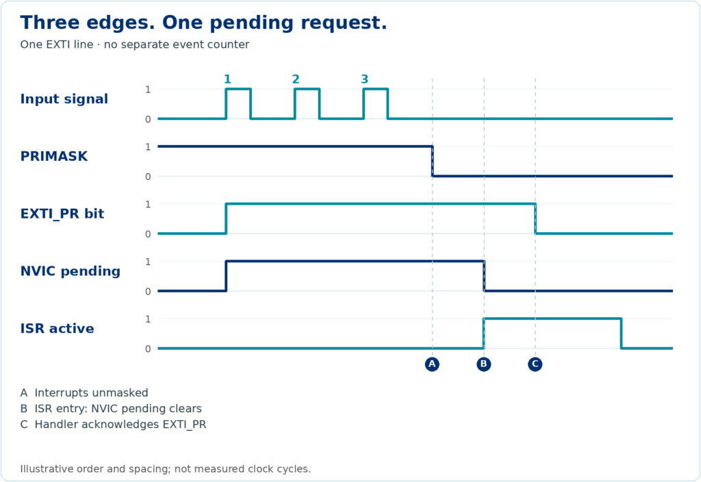
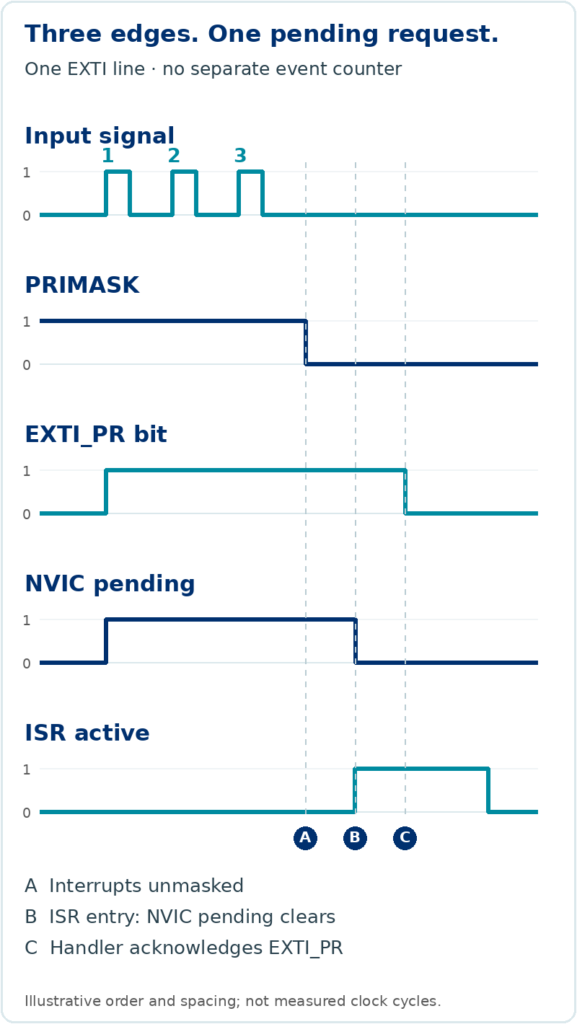
The peripheral remains configured throughout. No additional edge arrives during service, and no separate counter or buffer records the three edges.
The CPU may execute the ISR only once for those three edges. The pending indications tell software that at least one request occurred; they cannot reconstruct the original number of edges.
Assumptions for this illustration: all three edges are detected, the peripheral remains configured, no separate counter or buffer records them, no new edge arrives during servicing, and the handler acknowledges the source correctly. Physical pulses must meet the device’s input requirements.
2. Pending, active and masked: what is the difference?
These concepts are related, but they describe different things:
Pending
A request awaits service by the processor.
Active
The exception has been entered and has not completed. It can remain active while preempted by another handler.
Masked
A masking mechanism or priority restriction prevents the processor from taking the interrupt.
On Cortex-M4, setting PRIMASK prevents activation of configurable-priority exceptions; NMI and HardFault are not blocked by this mask. A request can still become pending and be serviced later. Masking does not create storage for each repeated request.
Masking with PRIMASK is different from disabling an individual IRQ through its NVIC enable bit. An NVIC-disabled interrupt can still become pending. Disabling the peripheral’s own request generation is yet another operation, whose effect depends on that peripheral.
Two state bits · four combinations
ACTIVE 0 · PENDING 0
Inactive
No active handler and no pending request.
ACTIVE 0 · PENDING 1
Pending
The request is waiting to be taken.
ACTIVE 1 · PENDING 0
Active
The handler has entered and has not completed.
ACTIVE 1 · PENDING 1
Active and pending
A further request is pending while the handler remains active.
Request
ISR entry
Further request
Selected transitions. Masking is a separate eligibility condition; it is not a fifth mutually exclusive exception state.
Read the interrupt configuration at both layers: the peripheral controls whether and how it generates requests; the NVIC and processor masks control whether the CPU can take them.
A pending interrupt does not guarantee that every physical event behind it has been preserved.
3. A practical example: why did the pulse counter undercount?
Suppose you are developing a motor-speed measurement system. A sensor produces pulses, and your firmware increments a variable whenever it services the sensor interrupt.
volatile uint32_t pulse_count = 0;

// Illustrative pseudocode: helper names need real peripheral handling.
void SENSOR_IRQHandler(void)
{
    if (sensor_interrupt_pending()) {
        acknowledge_sensor_interrupt();
        pulse_count++;
    }
}
The intent looks straightforward: each serviced notification increments the counter. But if several edges arrive while the interrupt is masked or its source remains pending, some edges may never be represented by separate handler executions.
Worked example · under the three-pulse assumptions
3
detected edges
All arrive before service
1
counter increment
One serviced notification
2
edges uncounted
No individual record survives
This group loses two increments. The 1,000-versus-997 table is a separate illustrative total.
| Measurement | Illustrative count |
|---|---|
| Pulses generated by the sensor | 1,000 |
| Pulses counted by the firmware | 997 |
| Difference | 3 |
These numbers illustrate a possible failure mode. They are not measured RaayanMini results, and they do not imply that every masking interval loses three pulses. If exactly three edges collapse into one increment, that particular group contributes two missing increments.
The real outcome depends on the hardware and timing. A hardware counter, capture register, FIFO or other storage may preserve some or all of the needed information. A single latched status flag only preserves an indication that something occurred.
On STM32F401 EXTI, the acknowledgement must clear the appropriate EXTI_PR bit by writing 1. The pseudocode above is not a complete board driver. Leaving the peripheral source asserted can make the ISR run again, even without another physical edge.
This explains why a debugger can show correct interrupt configuration while the application still reports an incorrect measurement: correct notification does not prove complete event recording.
4. Why the ISR alone cannot guarantee accurate event counting
An ISR is software executed in response to a request. It may process stored data, but the handler is not automatically the hardware mechanism that records each physical event.
A slowly operated button can make a simple interrupt-driven application appear reliable. A high-speed encoder, motor sensor or pulse generator can expose the limits much sooner. If events arrive before the CPU or peripheral can preserve and process them, application information can be lost.
Common contributors include:
- Interrupts are masked for too long.
- Higher-priority interrupts delay the handler.
- The CPU spends too much time in an ISR.
- The source provides only one latched status indication.
- Several events occur before software services or clears the peripheral status.
- The application assumes every physical edge produces a separate ISR entry.
Interrupt latency and event-storage capacity are different design concerns. Reducing latency can shorten the time before service. It cannot turn a one-bit flag into a queue, and it cannot recover events that were never recorded individually.
Checkpoint 01 Does a shorter ISR guarantee that every edge is counted?
No. A shorter handler reduces delay, but flags and storage still have finite capacity. Verify the worst-case event rate and the mechanism that records each occurrence.
5. What if another event arrives while the ISR is running?
An interrupt can be active and pending: its handler has not completed, and another request of the same IRQ is pending. If the request remains pending and becomes eligible after the current handler finishes, the processor can enter that handler again.
Several additional requests arriving while it is already pending still do not create a separate NVIC queue entry for each event. Keep these two cases distinct:
- Several events occur before the first ISR entry while the interrupt is pending.
- New events occur while the ISR is active and may cause another pending request.
The peripheral matters in both cases. A new edge after an EXTI flag has been cleared can set it again. Edges arriving while it remains set do not add a count to that bit. Clearing flags without understanding their semantics can also discard an indication that software has not processed.
A new EXTI edge during servicing
Edge before acknowledgement
- ISR enteredEXTI_PR = 1
- New edge arrivesStill 1; no extra count
- Handler acknowledgesEXTI_PR = 0
One latched bit cannot distinguish the two edges.
Edge after acknowledgement
- Handler acknowledgesEXTI_PR = 0
- New edge arrivesEXTI_PR becomes 1
- Request is retainedA further service can follow
The newly asserted request can require another handler entry.
Simplified timing cases. These are not a universal instruction to clear status first; use each peripheral’s required read-and-acknowledge sequence.
The NVIC automatically removes the pending state when it takes an interrupt, but that does not automatically acknowledge the peripheral source. A level-sensitive request that remains asserted can cause another ISR entry. Consult the peripheral’s interrupt-generation logic, status registers and acknowledgement rules.
Checkpoint 02 You need pulse width. Which timer feature helps?
Input capture. Capture timestamps at the required edges and calculate their interval, accounting for timer rate and wraparound. Use external counting when the requirement is the number of edges.
6. How can you capture events reliably?
Choose a mechanism that preserves the information your application needs, then verify its limits against the real signal.
A · COUNT EDGES
Use a hardware timer as an external event counter
Each accepted edge advances CNT
The CPU reads the accumulated count later.
If you need the number of pulses, a supported timer input can clock a hardware counter from external edges. The counter advances without the CPU entering an ISR for each pulse. Firmware can read it periodically or respond to appropriate timer conditions.
Applications: motor RPM, flow meters, industrial pulse counting and frequency measurement. For quadrature encoders, use a supported timer encoder mode when direction and both phases matter.
Check input routing, electrical levels, accepted frequency, filtering and prescalers. Account for overflow and read timing; an overflow flag itself is not an unlimited count of wraps.
B · RECORD TIME
Use input capture for precise timing
An edge latches a timer snapshot
120edge →CCR
120
The next capture can replace the stored value. Watch overcapture.
To measure the interval between edges, use input capture. A configured edge latches the timer’s counter value into a capture register, reducing dependence on when the CPU enters the ISR.
Applications: pulse width, frequency, ultrasonic echo timing, time-of-flight interfaces and motor timing, where the timer’s resolution and input capabilities meet the measurement requirements.
A basic capture channel has limited storage. On STM32F401, a capture sets CCxIFCCxOF
C · TRANSFER DATA
Use DMA for supported data streams
Supported peripheral → DMA → memory
Illustrative timestamp buffer. Transfer and consumption must keep up.
DMA can move peripheral data into memory with less CPU intervention. For a supported timer capture channel, it can transfer captured timestamps into a memory buffer without an ISR for every capture.
Applications: timer capture streams, ADC samples, serial receive data and continuous sensor acquisition on peripherals that provide the required requests.
DMA cannot automatically count arbitrary EXTI events. Verify the peripheral’s DMA request support, mapping, transfer rate and buffer management. A capture can overrun before transfer, and a memory buffer can fill before software consumes it.
D · BUFFER DATA
Use peripheral FIFOs and hardware buffers
A FIFO retains several items, if supported
Oldest → CPU
Generic peripheral example; not an STM32F401 USART FIFO claim.
Some communication peripherals provide FIFOs or other buffers, allowing several data items to accumulate while the CPU is busy. For example, a UART with an RX FIFO can retain multiple received bytes up to that FIFO’s capacity.
Applications: bursty communication and interfaces where processing may be delayed temporarily.
FIFO availability varies by MCU and peripheral; do not assume that the STM32F401 USART has a multi-byte receive FIFO. Monitor the relevant overrun indicators and drain or transfer data quickly enough.
E · RESPOND PROMPTLY
Keep interrupt service routines short
A short service path
The peripheral defines the required data and flag handling order.
A handler should generally do the essential work required by its peripheral:
- Identify the source that needs service.
- Read data and acknowledge status in the sequence the peripheral requires.
- Store essential information in an appropriate counter or buffer.
- Signal deferred processing when needed.
- Exit promptly.
Lengthy calculations, blocking calls and unnecessary processing delay other work. The exact read-and-clear sequence is peripheral-specific; “clear all flags first” is not a universal rule.
A short handler improves responsiveness. Hardware event capture is still needed when software cannot reliably service each occurrence in time.
7. Event notification and event recording
An interrupt requests the processor’s attention. A separate mechanism may preserve the event count, timestamp or data until the processor can deal with it.
| Mechanism | Purpose | Limitation |
|---|---|---|
| NVIC pending state | Marks an IRQ awaiting service | Does not count repeated requests |
| ISR software counter | Counts serviced notifications in this example | Cannot recover edges never recorded separately |
| Timer external counter | Counts supported input edges | Input limits, configuration and wraparound |
| Input capture | Latches timer values at edges | Limited capture storage and overcapture |
| Peripheral FIFO | Buffers several data items | Finite capacity; may overflow |
| DMA and memory buffer | Transfers supported data with less CPU work | Transfer and buffer limits still apply |
Ask these questions before choosing an interrupt-driven design:
- What tells the processor that an event needs attention? Identify the peripheral request, flags and NVIC IRQ.
- What preserves every required event or its data until it can be handled? Identify the counter, capture register or buffer and its capacity.
Test the shortest expected event interval against the longest processing delay. Use a scope or logic analyzer to check the physical signal, and compare it with hardware counts, capture data and overrun flags. ISR entry counts alone do not demonstrate complete event capture.
Design for the events your application must preserve
Three pulses arriving while a Cortex-M interrupt is masked do not guarantee three ISR entries. The NVIC tracks pending state, while the peripheral determines what event information is retained.
For a simple notification, an interrupt may be sufficient. For accurate pulse counting, timestamping or continuous acquisition, use the timer, capture and buffering facilities that match the measurement. Verify their capacities and timing on the actual hardware.
If every occurrence matters, make sure something records every occurrence. Your ISR may only be processing a notification.
Learn · Implement · Debug · Demonstrate
Understand interrupts on real hardware.
Explore STM32 peripheral drivers, timers, Embedded C, interrupt handling and practical debugging on RaayanMini with Kernel Masters.
Technical references:Arm Cortex-M4 Devices Generic User GuideST RM0368
 Admission for 6 months Embedded AI & IoT offline course at Hyderabad & Bangalore
 Course Fee: ₹12000 /-